In the right light: What ICH photostability tests are all about
Photostability tests are an essential part of stability testing for new active substances and finished pharmaceutical products (FPPs). The adoption of ICH guideline Q1B in 1996 paved the way for the fundamental standardization of the conditions for photostability tests.
The requirements are precisely defined: The samples should be exposed to visible light (VIS) for at least 1.2 million lux hours and to UVA for at least 200 watt hours per square meter.
Selection of light sources
ICH guideline Q1B offers two options for selecting light sources:
Option 1: Any light source that is designed to produce an output similar to the D65/ID65 emission standard such as an artificial daylight fluorescent lamp combining visible and ultraviolet (UV) outputs, xenon, or metal halide lamp. D65 is the internationally recognized standard for outdoor daylight as defined in ISO 10977 (1993). ID65 is the equivalent indoor indirect daylight standard.
For option 2, the same sample should be exposed to
- a cool white fluorescent lamp that is designed to produce an output similar to that specified in ISO 10977 (1993) and
- a UVA fluorescent lamp with a spectral distribution of 320 nm to 400 nm and a maximum energy emission of between 350 nm and 370 nm. A significant proportion of the waves must be within the ranges of 320 nm to 360 nm and 360 nm to 400 nm.
As such, the ICH guideline leaves open whether a single light source should be used to produce the entire D65 spectrum and the samples are illuminated in a single step, or if this happens in two steps with two different light sources (visible light and UVA).
Light sensors: Planar or spherical?
Two types of light sensors are available for ICH Q1B photostability tests – detectors with a flat sensor surface (planar sensors) and detectors with a spherical sensor surface (spherical sensors). There are two major differences between them – a planar sensor “calculates” the intensity of the radiation, whereas a spherical sensor measures the actual radiation intensity. A planar sensor calculates the amount of light incident on the sample at an angle lower than that encountered with vertical irradiation. This leads to an underestimation of the radiation energies, which results in excessive irradiation times and possibly false positive effects.
The second difference relates to the hemispheres of measurement. A planar sensor can only observe radiation above the sensor surface. It cannot record radiation that has an angle of incidence of either 0° or 180°, or radiation from below.

Figure 1:
Lambert’s cosine law states that radiation intensity decreases as angles become more oblique. As a result, the planar sensor needs cosine correction. The image shows the angle of incidence on the planar sensor surface with the percentage of incoming radiation in each case, compared to an angle of incidence of 90° (100%).
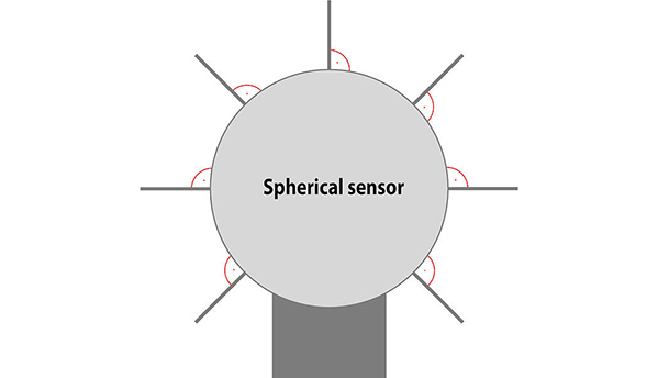
Figure 2:
The spherical sensor measures the actual radiation intensity from all directions, meaning that it even records scattered radiation. The radiation always hits the sensor at a 90° angle, which removes the need for cosine correction. The actual radiation intensity is measured rather than calculated.
BINDER ICH light modules
BINDER ICH light modules fulfill the requirements of ICH guideline Q1B, Option 2. The irradiance levels are designed so that a complete ICH photostability test can be carried out in just two days. The climate control in the chamber ensures that the preset climate is maintained at all times despite the high light intensity.
Each ICH light module consists of a supply unit and two illumination cassettes – one for the white light range (VIS) and one for the UVA range. The ICH LQC light module also contains two spherical light sensors. LQC stands for Light Quantum Control, our patented light photometry method for BINDER photostability tests.
Two spherical sensors that can be freely positioned control the light dosage of UVA (at least 200 watt hours per square meter) and visible light (at least 1.2 million lux hours). Once the desired light dose has been achieved, the corresponding illumination cassette is switched off.
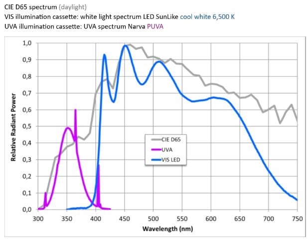
Emission spectra of the illumination cassettes
The latest LED technology with spectral characteristics similar to sunlight is used in the white light cassette (VIS). Special fluorescent tubes are used for the UVA range. The two illumination cassettes together reproduce the CIE-D65-like spectrum required by the ICH guideline perfectly.
The ICH light modules are compatible with the humidity test chambers from the KBF and KBF PRO series as well as with refrigerated incubators from the KB PRO series. They can be installed in a few simple steps and upgraded at any time.
Go to photostability test chambers